Operating an Arduino for a Year from Batteries
Sun 02 October 2011, By Alan Mitchell
The Arduino is a great product for producing a custom data collection system or controller. Programming is easy via a high-level language and a simple USB connection to the Arduino board. Incredible popularity has brought plenty of publicly available code and many add-on boards for interfacing sensors, storage, and wireless communications. However, most of my projects involve collecting data for multiple months, and access to mains power is often problematic. Battery-powered data collection is essential, but the Arduino quickly exhausts a battery when attempting to collect data for more than a few days. This article describes a technique for extending the battery life of an Arduino for many months.
The Arduino Uno board draws about 42 mA assuming no power draw from sensors or other components needed in your system. With a minimum supply voltage of 7 volts, the power consumption of the board is therefore 0.29 Watts. Sleep Mode is possible, but the onboard voltage regulator still has a quiescent current draw of 10 mA even when the processor is asleep. Assuming your task allows for sleeping most all of the time (like most of my data collection tasks), power consumption would be lowered to about 0.07 Watts utilizing sleep mode. An Alkaline AA battery has about 2.5 Watt-hours of energy; using three of these would give a battery pack containing 7.5 Watt-hours of energy. Ignoring voltage conversion losses, 7.5 Watt-hours of energy only powers the mostly-sleeping Arduino for 107 hours, a little over 4 days.
As the Sleep Mode article referenced above suggests, you can use the Atmega chip from the Arduino board on a custom board and use a much more efficient voltage regulator or possibly no regulator at all. This approach combined with using Sleep mode could dramatically lower the power consumption of the system. However, you then lose access to the numerous accessory shields available for the Arduino, and many of the ease-of-use advantages of the Arduino are lost. For a data collection project I'm currently working on, I've chosen a different approach. I am building a small power controller board that will only periodically apply power to the Arduino board, and then after the Arduino is done reading a sensor and wirelessly sending its data, the Arduino will signal completion of its tasks to the power controller and the controller will cut power to the Arduino. All Arduino power consumption will be eliminated at that point until the next power-on cycle. The power controller board itself will obviously use some energy, but using sleep mode for that microcontroller and powering the power controller circuit directly from the battery without a regulator will lower its power consumption during periods when the Arduino is not on to an average of about 11 microWatts. A basic block diagram of the system is shown below.
Basic Diagram of the Low Power Arduino System
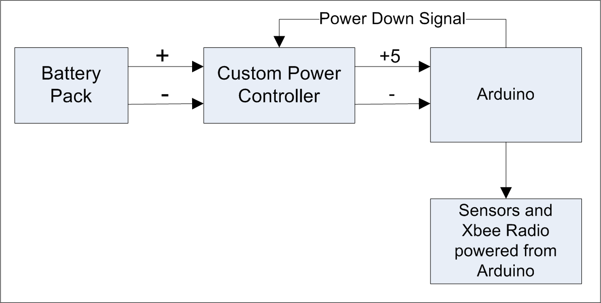
If the one of the goals is maintaining the ease-of-use advantage of the Arduino, having to build a separate, custom power controller circuit seems to defeat that goal. However, the power controller circuit can be used without re-design for a wide variety of Arduino projects. The only power controller parameter that varies between projects is the length of time between each successive power up of the Arduino.
There are clearly some limitations with this approach. If your application requires the Arduino to set outputs for control purposes, these outputs will be lost each time the Arduino is powered down. So, this power-saving approach is really meant for data acquisition applications, not control applications. Also, if you need to retain data or settings between each power-on cycle of the Arduino, you will need to use the EEPROM memory in the Arduino, as that memory is unaffected by loss of Arduino power.
So, what kind of battery life can be achieved with this strategy? To answer this question, you need to know how long the Arduino will be powered up and how long it will be totally off. For my current project, I need to read a sensor and wirelessly transmit the results every 10 minutes. Each time the power controller circuit applies power to the Arduino, the Arduino has to boot up, read the sensor and then send the result via an Xbee radio. I have measured the boot-up time for the Arduino Uno, which equals about 72 milliseconds. (This is substantially faster than the earlier Arduino Duemilanove, which took a full 1.45 seconds to boot up. Clearly if you intend to use this power-saving approach, you would want to use the fast-booting Uno model.) Reading the sensor for my project will take about 10 milliseconds. Until I measure more carefully the Xbee boot-up and transmit time, I will conservatively assume that the Xbee process pushes the power-on duration up to a full one second.
As well as knowing the Arduino duty cycle, you also need to know power consumption of the Arduino and accessories when it is On. In my project, I will apply power to the Arduino through the 5V pin, so that I can avoid some of the voltage regulator losses on the Arduino board. Adding in the sensor and Xbee power consumption, I estimate an average current draw of 70 mA during the period while the Arduino is powered up. So, power consumption during the power-on time is 0.07 A x 5 V = 0.35 Watt. But, the circuitry is only powered up for 1 second out of the 10 minute repeat interval, so the average power draw is 1 sec / 600 sec x 0.35 W = 0.000583 W or 0.583 mW. My custom power controller board produces the 5 volts necessary for the Arduino board through use of an 85% efficient boost switching power converter. So, the 0.583 mW average power draw of the Arduino takes 0.583 mW / 0.85 = 0.686 mW from the battery on average. Adding in the 11 microWatt draw of the custom power controller board gives a total power consumption of 0.697 mW. With a 3 x AA Alkaline battery pack having 7.5 Watt-hours of energy, my project should see a 7,500 mW-hrs / 0.697 mW = 10,800 hour battery life, or about 15 months, a substantial improvement over the 4 day battery life achievable through the standard Arduino setup.
NOTE: A commercial product is now available from Adafruit that performs this power controller task. See the Adafruit TPL5110 Low Power Timer Breakout product.
Design of the Power Controller Circuit
The power controller really has two tasks: 1) convert the voltage from the battery pack to a level suitable for the Arduino, and 2) turn on power to the Arduino when a reading should be taken and shut off power to the Arduino at other times. The voltage conversion task can be handled by a Boost switching power converter. I didn't want to reinvent the wheel here so tried to find a suitable off-the-shelf module to use for this purpose. I ran into some challenges that I'll talk about later. For task 2, controlling when power is applied to the Arduino, I used a PIC12F683 microcontroller that controls the Shutdown pin (or Enable pin, depending on the boost converter) and also controls a MOSFET switch to solidly disconnect the Arduino from the boost converter for converters that don't isolate the output load when in shutdown mode. The schematic of the design is shown below. (Pardon my hand drawing!)
Power Controller Schematic
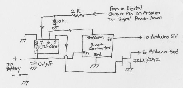
The PIC12F683 has the task of periodically switching On the power to the Arduino and then responding to a signal back from the Arduino to turn the power Off. Three I/O pins are used on the PIC. Pin 7 is the GP0 I/O pin on the PIC and it configured as an input. This pin accepts a signal from a digital output pin on the Arduino. The Arduino code should raise this output High when it has completed it's processing. That action tells the Power Controller board that it is time to shutdown the power to the Arduino until the next cycle. The 10K resistor in the schematic is used to pull down the input low except during times when it is raised High by the Arduino. The 2K resistor makes the PIC circuit tolerant of the 5V logic levels present on many of the Arduino boards (the cirucit above also works with 3.3V logic).
Pin 6 on the PIC is the GP1 I/O pin and is configured as an output to control the Shutdown (or Enable) input on the Boost Converter. When power is not being applied to the Arduino, the boost convert should be put into a low-power state so that battery energy is conserved. This pin serves that purpose.
Pin 5 on the PIC is the GP2 I/O pin and is configured as on output to control a MOSFET transistor that is used to isolate the Arduino from the Boost Converter. For many boost converters, simply shutting down or disabling the converter does not disconnect the output load. Instead, the converter will stop its voltage-boosting function but will leave the output of the converter essentially connected to the input battery. Voltage drops from the boosted 5V, but will approximately equal the battery voltage. That level of output voltage will probably cause the Arduino to operate, perhaps unreliably, and will certainly cause the Arduino to draw substantial current. So, the MOSFET transistor in the schematic is used to fully disconnect the Arduino from the boost converter. Later when I discuss boost converters, I'll talk about a model that does not need this transistor, as it is already designed to fully disconnect the output load during shutdown. Unfortunately, I didn't have access to this particular boost converter when building the first power controller.
The PIC code is relatively simple and is listed at the end of this post. The general approach is to repeatedly put the PIC to sleep and then have it wake up when the Watchdog timer expires (after about 4.5 seconds for the settings I use). After a suitable number of Sleep/Wakeup cycles, power is applied to the Arduino util the power-down signal is received back from the Arduino. If that signal is never received, the controller times out after a certain number of seconds and shuts down the Arduino power anyway.
Because I don't use any of the special PIC features except the Watchdog timer, the current consumption of the PIC during sleep falls to about 1.5 uA (micro-amps) (or about 7 micro-Watts for the 3 x AA battery pack I am using). Achieving this extremely low power level requires that you do not use the Brown-out protection circuitry of the PIC, as that feature increases sleep-mode current draw to about 60 uA.
While you can get the PIC to use a miserly 1.5 uA during sleep, many boost converters are not so low-power when shut down. The boost converter in my initial prototype uses 35 uA when in shutdown mode, more than 20 times what the PIC uses. So, the sleep-mode power consumption of my prototype circuit is about (1.5 uA + 35 uA) x 4.5 V = 164 micro-Watts, not particularly impressive. This brings me to a discussion of boost converters and the various challenges I faced with that part of the design.
Boost Converters
My initial choice for a boost converter was the LiPower unit from SparkFun. My plan was to use a MOSFET transistor on the input side of the converter to entirely remove power from the converter in the period between Arduino power On periods. This would reduce the sleep power consumption of the boost converter to zero. Unfortunately, the large and high-frequency switching currents drawn from the battery during power On periods wreaked havoc with the particular MOSFET (IRLU024Z) that I was using. I wasn't able to achieve a low Drain-Source voltage when the MOSFET was On, so the MOSFET wasn't being a very good power switch. I'm sure someone more knowledgeable about MOSFETs could have solved this problem with a different MOSFET, but I was eager to get something working, so I moved on.
I decided to change to a design where I always powered the boost converter, but I would use a shutdown or enable pin to put the boost converter into a low power state when the Arduino wasn't being powered. The LiPower module used a regulator chip that had an Enable pin, but the Enable pin was not accessible through the module terminals. The surface-mount circuitry also made it hard for me to modify the module to access the Enable pin. So, I next tried a Minty Boost v 2.0 module, which I happened to have in the drawer. The LTC1302 regulator chip used in this module has a shutdown pin, but it also was not wired to a terminal in the module. However, because the regulator utilized a DIP package, I was able to bend upward the shutdown lead on the DIP, removing it from the module circuit, and I soldered directly to the pin to access it.
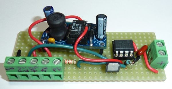
Below is a picture of the prototype using the Minty Boost. The screw terminals to the front left of pic include the output power terminals for the Arduino plus some other terminals to facilitate switching other power sources in addition to the Minty Boost. The battery input terminals are on the right side of the circuit board.
Minty Boost Prototype
Here is a calculation of the expected battery life with the Minty Boost prototype. The calculation assumes a 3 x AA battery pack having 7.5 Watt-hours of energy and an Arduino circuit using 70 mA for 1 second out of every 10 minutes. The Arduino power-on load is therefore 5 V x 70 mA = 350 mW.
Battery Life calculation using Minty Boost: As calculated before, when the Arduino is Off, power consumption of the power controller board is 164 uW (micro-Watts) . When the Arduino is On, the battery draw is the 350 mW Arduino load divided by the converter efficiency, which I measured to be about 75%. 350 mW / 0.75 = 467 mW. Weighting On and Off consumption: 1 sec / 600 sec x 467 mW + 599 sec / 600 sec x 0.164 mW = 0.942 mW. Battery life is 7,500 mW-hours / 0.942 mW = 7,960 hours or about 11 months.
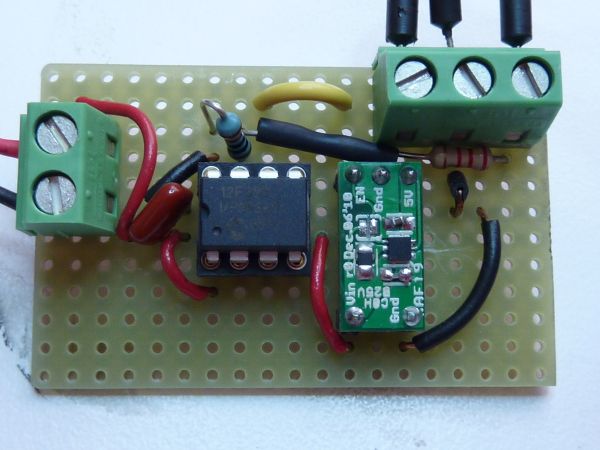
I subsequently found a different boost converter module that is a much better fit for my application. The module's design is based on the Texas Instruments TPS61240 chip. It has an enable pin and claims to have less than 1 uA current draw when disabled! Also, when the chip is disabled, the output is disconnected from the input battery, making the MOSFET in the above circuit unnecessary. A converter board has been designed by Circuits@Home. Because the MOSFET is not needed, I can use this circuit with a 2 x AA battery pack, as I do not have any worries about sufficient battery voltage to turn on the MOSFET. Below is a picture of the Arduino power controller board utilizing the Circuits@Home module.
Power Controller with the TPS61240 Converter
Because the TPS61240 isolates the output load when the chip is disabled, I did not need the MOSFET switch that I used in the prior Power Controller board. As well as having that advantage, the shutdown current for the TPS61240 chip is very low. I measured about 1.5 uA current draw of the entire power controller board when the PIC was asleep and the boost converter was disabled.
The power controller was built on a SB300 perfboard (cut with a Dremel to reduce its width). I've found these to be inexpensive and effective PCBs for building one-off projects.
Below is a picture of the power controller in use controlling an Arduino with a Data Logging shield.
Power Controller with Arduino
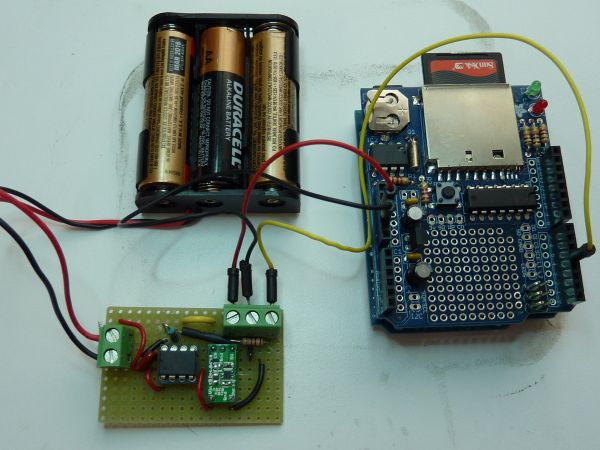
In this application, the Power Controller periodically applies power to the Arduino + data logging shield. While powered, the Arduino can read sensors, read the real-time clock on the shield, and then store the data on the shield's SD card. After doing so, the Arduino raises the power-down line back to the Power Controller and the controller removes power from the Arduino. Multiple months of battery life can be achieved with this arrangement.
Battery Life calculation using TPS61240 Boost Converter: When the Arduino is Off, the power consumption of the controller should be (1.5 uA PIC sleep + 1.0 uA converter shutdown) x 4.5 V = 11.3 uW. The regulator specs indicate an efficiency of over 85% at my load condtions. So Arduino On power consumption is 350 mW / 0.85 = 412 mW. Weighting On and Off consumption: 1 sec / 600 sec x 412 mW + 599 sec / 600 sec x 0.0113 mW = 0.698 mW. Battery life is 7,500 mW-hours / 0.698 mW = 10,750 hours or about 15 months.
For the past month I have been measuring battery drain-down using the original less-efficient Minty Boost version of the Power Controller and a similar Arduino + data logging shield load. Measurements on battery drain-down indicate that battery life should live up to the calculations presented in this article.
Below is the PIC code for the Power Controller, written for the CCS C compiler (sometimes know as the PICC compiler). I tried to comment the code enough so that it could be reproduced in another language or for a different microcontroller.
#include <12F683.h>
// Definitely turn off the Brownout protection, as that feature
// increases sleep mode current draw by about 60 uA.
#fuses INTRC_IO,WDT,NOPROTECT,PUT,NOBROWNOUT
#use delay(clock=4000000)

// Pin Assignments:
// A0:  The Power-Down input to this controller.  The Arduino or circuit being
//      fed power must raise this pin High when it has completed its tasks.
//      This power controller will then cut off power to the output terminals.
// A1:  This pin is wired to the Shutdown pin on the Boost converter.  The PIC
//      will set this pin High when it wants shut-down the Boost converter.
// A2:  This pin is wired to the Gate on the MOSFET that connects or disconnects
//      the output of the Boost converter to the output terminals.  The gate is
//      raised high to turn on the MOSFET and connect the Boost converter to the
//      output terminals
// All other IO pins are unused.

main() {

   // The 'interval' variable controls how often power is fed through to the
   // output of the controller.  The 'interval' value times 4.5 seconds gives
   // that duration in seconds.
   int16 interval=133;    // value of 133 is about 10 minutes

   // The 'timeout' variable is a backstop in case the Arduino does not signal
   // back that it is finished using power.  'timeout' times 0.01 seconds is the
   // maximum time that power will be fed through to the output of the controller.
   int16 timeout=300;   // value of 300 is 3 second timeout

   int16 ct=0;    // tracks the number Watchdog timeouts since last power-on.
   int16 i;       // used to implement the power-down timeout.

   // shutdown boost converter and turn off power switch initially
   output_high(PIN_A1);
   output_low(PIN_A2);

   // make all other pins outputs and drive low to eliminate any possible
   // switching currents that may increase power consumption.
   output_low(PIN_A3);
   output_low(PIN_A4);
   output_low(PIN_A5);

   // Set Watchdog prescaler.  WDT_DIV_1024 gives about a 4.5 second
   // watchdog period on my particular PIC, but this can vary substantially with
   // voltage, temperature, and the particular microcontroller chip.
   setup_wdt(WDT_DIV_1024);

   while (TRUE) {
      ct++;
      if (ct >= interval) {
         // enough Watchdog intervals have passed to power the output.

         ct = 0;   // reset counter that tracks Watchdog intervals

         // Enable boost converter and connect converter output to output terminals.
         output_low(PIN_A1);
         output_high(PIN_A2);

         // Wait for Arduino to boot up before checking for power down signal.
         delay_ms(140);      // Uno takes about 70 ms to boot up, but double that to be sure.

         // wait for a power-down signal, but timeout after a certain amount of
         // time.
         for (i=0; i